RG59 Siamese Coax Cable Wiring Guide
for Analog CCTV Cameras & HD Security Cameras (HD-TVI, AHD, HD-SDI, HD-CVI)

This guide will educate professional and DIY installers on techniques for wiring CCTV cameras and video surveillance systems using
spools of RG59 Siamese coax cable. This guide applies to security cameras that use coax cable to transmit video to DVRs and monitors. This includes analog CCTV cameras and the following HD security camera types: HD-TVI, AHD, HD-SDI, HD-CVI.
We also have this guide on how-to wire a security camera system using pre-made Siamese cables. The following topics will be discussed in this article.
One of the best cable options for video over coax type surveillance cameras is to use spools of RG59 Siamese cable. This allows the installer to cut the cable to the exact length needed, but requires that the BNC connectors be attached to the cable. CCTV Camera Pros has 500 and 1000 foot spools available. Complete packages are also available that include BNC connectors, cutting tool, and crimping tools. You can find
RG59 cable & complete wiring packages including installations tools here.
RG59 Siamese cable is a heavily shielded cable which contains an RG59 COAX cable for video and pair of 18 gauge 2 conductor power wires in one jacket. The advantages to using RG59 cable for CCTV camera installation is that it is more durable than most pre-made camera cables and can be run in long distances without interference. You can also cut each cable run to the exact length that you need which makes the cabling part of the installation neat.
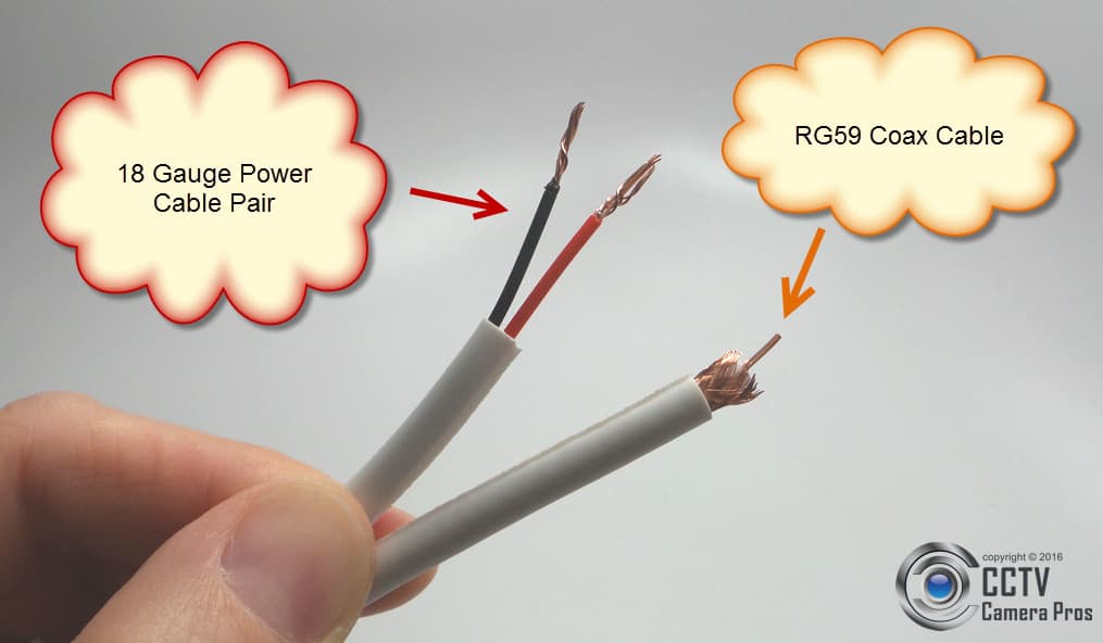
The above picture shows a close-up of RG59 cable. You can see the 18 gauge power cable and the RG59 coax portions of the cable clearly.
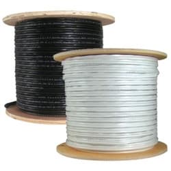
RG59 Siamese cable comes in 500 and 1000 foot spools. White and black cable is typically available in case your cable is visually exposed and you have a preference in color.
CCTV cameras (analog and HD types) and the surveillance DVRs that they connect to use BNC connectors for video input / output. CCTV cameras always have a BNC female as their video output and CCTV and HD surveillance DVRs almost always have a BNC female inputs for each video channel. This means that the installer must attach a BNC male connector to each end of the RG59 cable run.
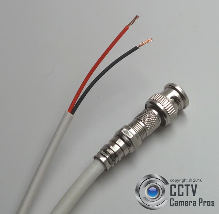
The above image shows RG59 cable with a BNC male attached to it. There are many different types of BNC connectors available. Each requires a slightly different technique and tool for attaching the connector to the cable. A favorite method among professional installers is attaching an F connector to the coax cable, then screwing on a BNC connector.
The method of how-to attach a BNC connector to RG59 using a crimp on F connector is described in detail here.
How-to Attach BNC Connectors - Video Demos
The below videos demonstrate three different ways of how to attach BNC connectors to RG59 cable. All three methods and connector types are very popular among professional and DIY installers.
How to Attach a Compression F Connector & BNC Male to F Female to RG59
This video uses a very popular method of attaching a BNC connector to RG59. The installer first attached a
male F connector (compression type) to the cable. Then a BNC male to F female is screwed on. This technique is popular with security installers because compression connections are known to be extremely secure and F compression connectors are very easy to attach. Installers can then attach a BNC end or an RCA end to the F connection.
How to Attach a BNC Crimp-on Connector to RG59
This video shows customers how to attach a
2 piece BNC crimp-on connector to RG59. This is another very popular method for attaching BNC male connectors to RG59 and RG6 coax cable. This technique provides a very secure and reliable connection that will last.
How to Attach a BNC Twist-On Connector to RG59
This video shows customers how to attach a
BNC twist-on connector to RG59. One of the nice things about twist on type connectors is they do not require any special tool to attach them besides a coax cable stripper tool.
Most 12V DC security cameras (analog CCTV and high definition) have a 2.1mm DC power plug (male) connected to the power input of the camera. If you are using a 24VAC powered camera, dual voltage camera, or any camera that has a wire terminal block to connect power, you can
skip to this section of these instructions.
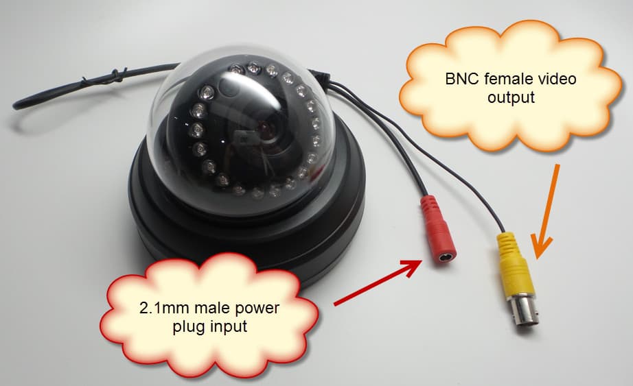
To connect the 18/2 power portion of the RG59 Siamese cable to a camera with a 2.1mm power plug, you must attach a
PT-3 power lead.
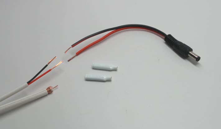
Butt connectors, B connectors, or another wire connector type of the installer's choice can be used to attach the 18 gauge power cables to the power lead.
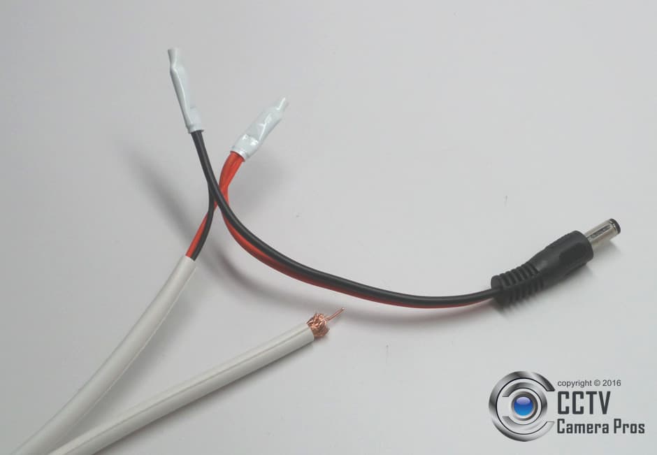
This images shows the cable with a DC power lead attached using B connectors.
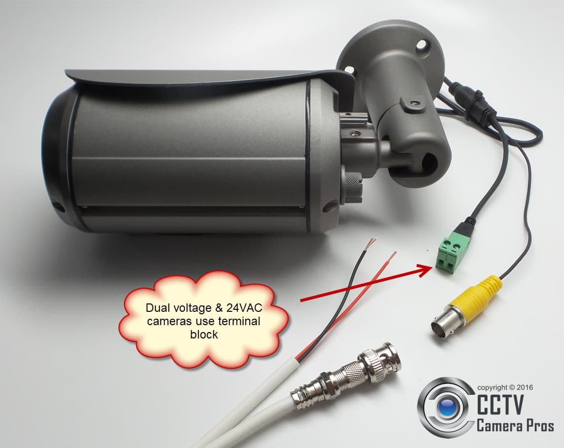
Most dual voltage security cameras (ones that can use a 12V DC or 24VAC power supply) do not have a 2.1mm plug attached to their power cable. Above is a dual voltage
1080p HD CCTV camera. Notice the power terminal block that is used instead of a 2.1mm power plug. The 18/2 power cables of the RG59 Siamese can attach directly to this terminal block by inserting into the slots, then securing the cable with screws.
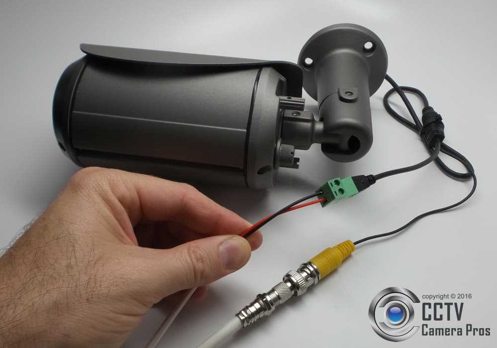
This is what it looks like with the 18/2 cable attached to the power terminal block of the security camera.
The above wiring diagram shows how a dual voltage camera can be wired using pre-made Siamese cables.
Multi-camera power supply boxes are used to centralize the power for video surveillance systems. If you are using individual power transformers to power your cameras, please refer to the
how-to use individual power supplies with RG59 cable section of this guide.
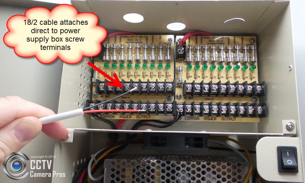
To wire security cameras to a
power supply box with RG59 Siamese cable, the 18/2 power wire connects directly to the screw terminals of the power supply box.
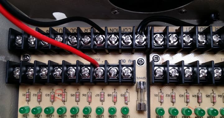
Here is a close-up of the 18/2 cable attached to the power supply box. Power supply boxes are typically wall mounted near the surveillance DVR.
Surveillance System Install - 12V DC Camera and Power Supply Box
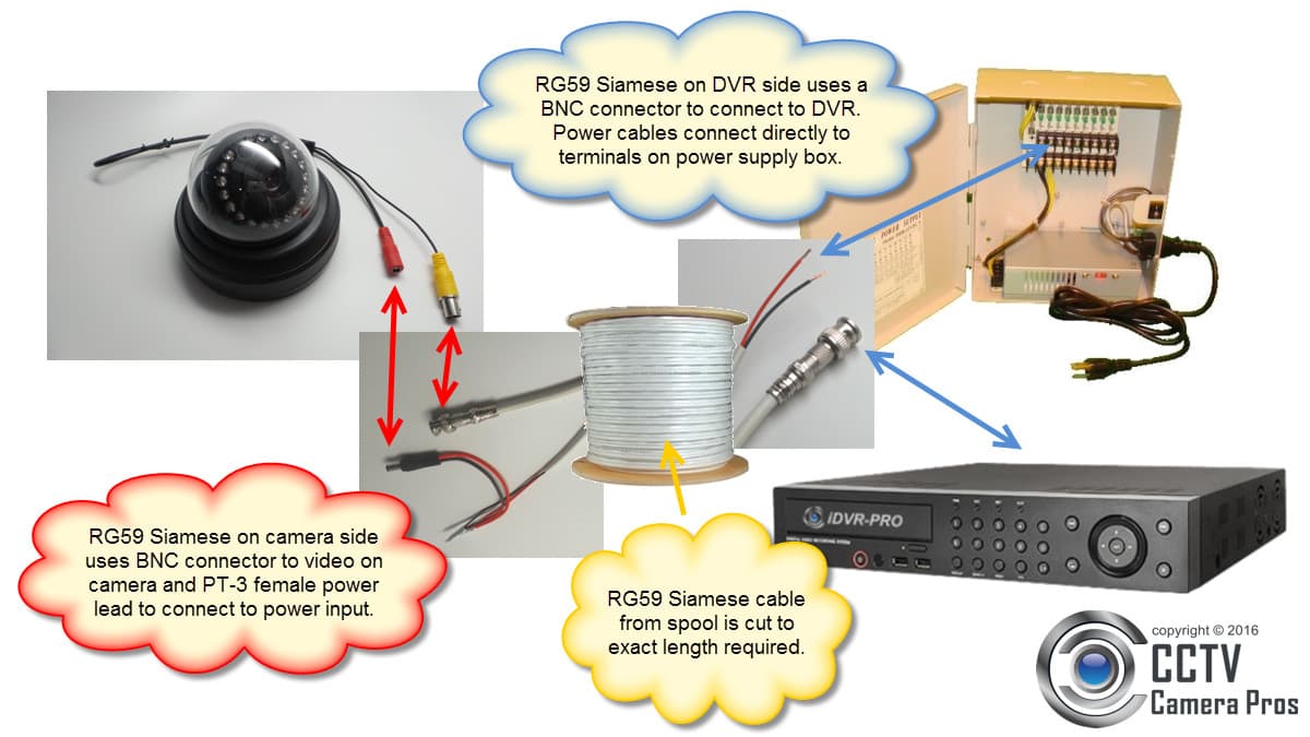
Here is a complete CCTV camera system cable diagram that uses a RG59 cable, a
1080p HD surveillance camera (12V DC powered), a hybrid HD / analog CCTV DVR, and a 12V DC multi-camera power distribution box. You may click on the image for a higher resolution view.
- The RG59 Siamese cable is cut to the exact length required.
- On the camera side of the cable, a BNC connector is attached to the RG59 coax and a PT-3 power lead is attached to the 18/2 power cable.
- On the DVR side, a BNC connector allows the coax cable to connect to the video input of the DVR and the raw 18/2 power wire connects directly to one of the ports on the power supply box.
- These steps are repeated for each 12V DC camera that your system uses.
Surveillance System Install - Dual Voltage Camera and Power Supply Box
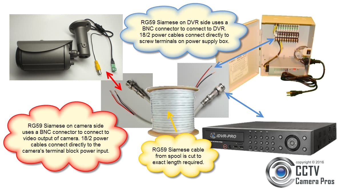
Here is a complete security camera system installation diagram that uses a RG59 cable, a
1080p HD CCTV camera (dual voltage), a hybrid AHD / HD-TVI / analog CCTV DVR, and a power supply box - which can be 12V DC or 24VAC. You may click on the image for a higher resolution view.
- The RG59 Siamese cable is cut to the exact length required.
- On the camera side of the cable, a BNC connector is attached to the RG59 coax to connect to the video output of the camera. The 18/2 power cable connects to the terminal power input block via built-in screws.
- On the DVR side, a BNC connector allows the coax cable to connect to the video input of the DVR and the raw 18/2 power wire connects directly to one of the ports on the power supply box.
- These steps are repeated for each 24VAC and dual voltage cameras that accept raw power wire for power input.
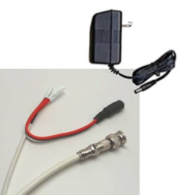
If you plan to use individual power transformers to power your security cameras (instead of a power supply box), you must attach a
PT-4 mail power cable lead on the DVR side of the cable run. This allows the 18/2 power cable to attach to the 2.1mm female power lead of the power transformer.
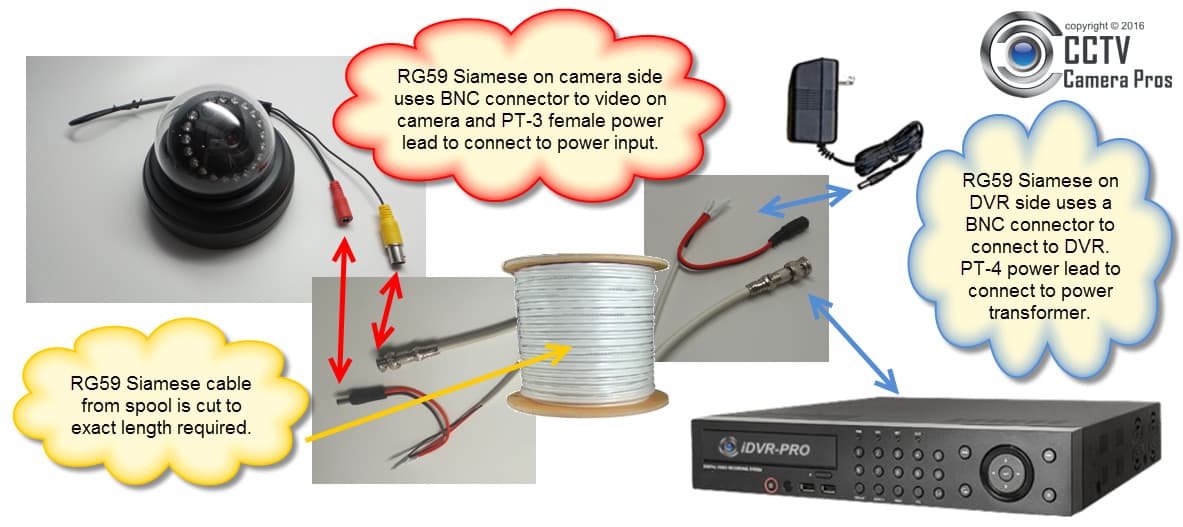
Here is a complete security camera system installation diagram that uses a RG59 cable with an individual power transformer powering the camera from the DVR side of the cable run. You may click on the image for a higher resolution view.
- The RG59 Siamese cable is cut to the exact length required.
- On the camera side of the cable, a BNC connector is attached to the RG59 coax and a PT-3 power lead is attached to the 18/2 power cable.
- On the DVR side, a BNC connector allows the coax cable to connect to the video input of the DVR and PT-4 2.1mm male power lead is attached to the 18/2 power wire with B connectors so that the power cable can attach to a individual power transformer - which has a 2.1mm female power connector.
Available in CCTV Camera Pros Mobile App


This article, and many others, are also available in CCTV Camera Pros mobile app for iOS and Android. Please download the app to keep up with the latest installation discussions, product demonstration videos, and special offers / coupons.
About the Author

This article was written by
Mike Haldas, co-founder and managing partner of CCTV Camera Pros. If you have any questions about how to wire a security camera system using pre-made camera cables, please email me at mike@cctvcamerapros.net.
|


