CAT-5 Wiring Diagram & Crossover Cable Diagram
This
CAT5 wiring diagram and crossover cable diagram will teach an installer how to correctly assemble a CAT-5 cable with RJ45 connectors for regular network cables as well as crossover cables. Please note that these instructions are the same for CAT-6 cable and and other type of 4 twisted pair network cable. Please also note that in this article, we are referring to CAT5e, CAT5, and CAT-5 as all the same type of cable. CAT5 Ethernet cable.

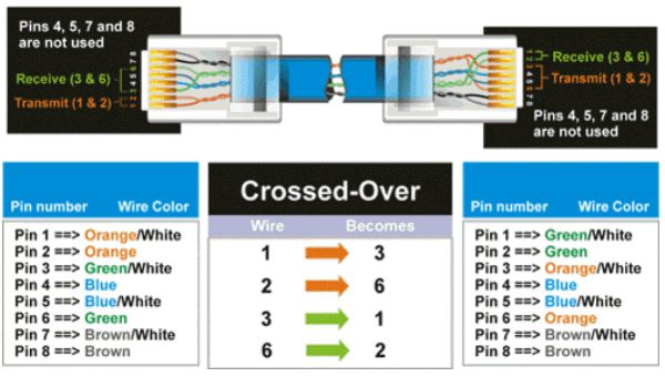
This diagram shows the sequence of colored wires used for EAI standard Ethernet cable / TIA-568B. Please note the CAT5 wire order. It must be consistent on both ends of the cable.

This diagram shows the sequence of colored wires used for EAI cross-over cable / TIA-568A standard.
The T568A and T568B standards highlight the significance of the orange and green pairs, with T568B involving swapping the positions of these color-coded pairs. Please note the CAT-5 wire order.
Cat5 Wiring Standards
When wiring a Cat5 cable, it’s crucial to follow one of the two main wiring standards: T568A or T568B. These standards determine the order and color orientation of the wires in each RJ45 connector at both ends of the cable. Using the correct wiring scheme ensures maximum signal quality and compatibility with network devices.
The T568A and T568B wiring schemes differ in the arrangement of the wire pairs. While both standards are widely accepted, T568B is more commonly used in the United States. It’s important to use the same wiring scheme on both ends of the cable to ensure a proper connection. Refer to the appropriate wiring diagram to achieve the correct configuration.
Wiring a Cat5 Cable: Step-by-Step Guide
Wiring your own Cat5 Ethernet cables can be a straightforward process if you have the right tools and follow these steps:
-
Gather the required components: You will need Cat5 Ethernet cables, wire cutters, wire strippers, RJ45 connectors, and a crimping tool.
-
Cut and strip the cable ends: Use your wire cutters to cut both ends of the Cat5 cable to the desired length. Leave a little extra length to work with. Then, use the wire strippers to remove 1 to 2 inches of the outer sheath jacket from both ends, exposing the 4 internal wire pairs.
-
Untwist and organize wire pairs: Carefully untwist each wire pair at the end and neatly align them according to the wiring scheme you’re using (T568A or T568B).
-
Insert the wires into the RJ45 plug: Hold the RJ45 connector clip side down and insert the aligned wires firmly into the grooves following your wiring diagram (A or B).
-
Crimp the RJ45 connector: Place the loaded RJ45 connector into the crimping tool. Make sure it’s fully seated flush in the crimper. Go ahead and crimp it down firmly. This may take considerable force to punch down and make solid contact.
-
Repeat steps on the other end: Repeat steps 2-5 for the other end of the Cat5 cable. It’s crucial both ends follow the same wiring scheme for straight-through connections.
By following these steps, you can create reliable and high-quality Cat5 Ethernet cables for your networking needs.
CAT-5 Cable Installation
EIA/TIA-568B, also known as standard Ethernet, is the type of CAT-5 connection used to connect
IP security cameras and network video recorders (NVRs) in IP surveillance systems. If you are creating a crossover cable, please click here for the crossover cable diagram.
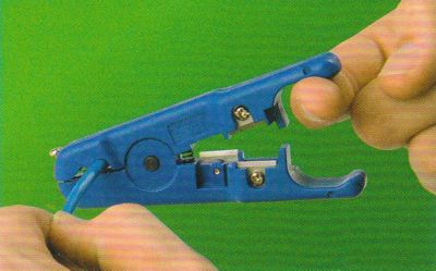
- Using a cable stripping tool, strip about 1/3"of the out jacket of the cat-5 cable. Be sure not to strip or damage any of the pairs of inner cables.

- Assemble the pairs of wires in the following order for network cables (EAI standard / TIA-568B).

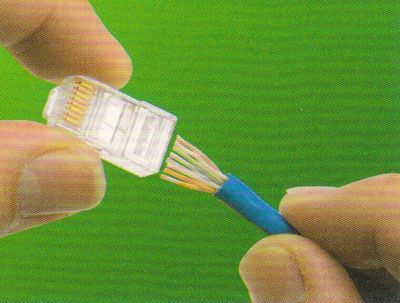
- Insert the wires into the RJ45 jack as seen below. Be sure to keep the wires in the correct order.

- Insert the RJ45 connector into the crimping tool (again carefully make sure the wires stay inserted in the correct order). Crimp down firmly on the crimping tool to permanently attach the RJ45 to the CAT5 cable.

Crossover Cable Diagram
To create a crossover cable with cat-5 cable follow the same instructions as above for
CAT-5 wiring except when you get to step #2, use the below crossover cable diagram:

What is a Cat5 Cable?
A Cat5 cable, also known as a Category 5 cable, is a type of twisted pair cable used extensively in computer networking and telecommunications. This cable consists of four twisted pairs of copper wires, which are terminated by RJ45 connectors. The twisting of the wire pairs helps to reduce electromagnetic interference, ensuring a more stable and reliable connection.
Cat5 cables are capable of transmitting data at speeds up to 100 Mbps, making them suitable for most Local Area Network (LAN) connections. Additionally, these cables can provide Power over Ethernet (PoE), which allows devices such as
IP cameras and Wi-Fi access points to receive power through the same cable used for data transmission. This dual functionality makes Cat5 cables a versatile and cost-effective solution for various networking needs.
Ethernet Cable Categories
Ethernet cables come in several categories, each designed to meet specific performance standards and capabilities. Here are the most common categories:
-
Cat5: This category supports data transmission speeds up to 100 Mbps and is commonly used for standard LAN connections. It is suitable for basic networking needs and is often found in residential and small business environments.
-
Cat5e: An enhanced version of Cat5, Cat5e supports speeds up to 1 Gbps, making it ideal for Gigabit Ethernet connections. It offers improved performance by reducing crosstalk and interference, ensuring a more stable and faster connection.
-
Cat6: Cat6 cables support speeds up to 10 Gbps over shorter distances and are commonly used in high-speed networking applications. They offer better performance and reduced crosstalk compared to Cat5e cables.
-
Cat6a: An augmented version of Cat6, Cat6a supports speeds up to 10 Gbps over longer distances. It is designed for high-speed networking applications and provides superior performance in terms of crosstalk and interference.
-
Cat7: Cat7 cables support speeds up to 40 Gbps and are used in high-speed networking applications where maximum performance is required. They offer the highest level of shielding and reduced interference among all Ethernet cable categories.
Troubleshooting Common Issues
Incorrect wiring of an Ethernet cable can lead to several issues that may affect your network’s performance. Here are some common problems and their potential consequences:
-
No network connection: If the wires within the cable are not arranged and connected according to the Cat5 cable diagram, your devices may fail to communicate with each other. This can result in a complete loss of network connectivity.
-
Intermittent connection: An unstable, intermittent connection can manifest as random disconnections, slow data transfer rates, or even packet loss during data transmission. This issue is often caused by improper wiring or loose connections.
-
Cross-talk and interference: Cross-talk occurs when signals from one pair of wires interfere with signals from another. This can degrade the quality of your connection and may even result in data loss. Proper wiring of Ethernet cables following the Cat5 cable diagram reduces cross-talk and interference.
-
Damage to network devices: In extreme cases, incorrectly wiring an Ethernet cable could potentially damage your network devices. This scenario is rare, but it can occur if the miswiring results in a short circuit.
By ensuring that your Ethernet cables are wired correctly according to the Cat5 cable diagram, you can avoid these common issues and maintain a stable and efficient network.

|
Author
This article is maintained by
Mike Haldas, co-founder and managing partner of CCTV Camera Pros. Questions about this page can be directed to mike@cctvcamerapros.net.
|
|
CCTV Equipment
|
Video Surveillance Systems
|
Network Surveillance Equipment
|
|
|
|
|
|
|
|


